
Papers in Houston, TX
The Texas Medical Center’s Tallest Building
Memorial Hermann Medical Plaza
Edward J. Ulrich, Jr.

Abstract
This paper focuses on the contribution of drilled piers and their ability to turn a good project into a spectacular project. Drilled piers and shallow foundations eliminated temporary retention systems to support the Texas Medical Center’s tallest building at 32 stories. Reduced development costs amounted to over $1 million when we were able to increase useable basement space, eliminate cantilevered floors for one full bay to the property line, and eliminate interior perimeter columns to effectively minimize the depth of basement excavation. The unique foundation features of the building and parking garage are highlighted along with the structural concepts for basement wall design.
We designed drilled piers that formed the temporary and permanent basement wall, along with the sole support. As the drilled pier design was for the exterior column loads that reinforced the concrete tower, installation by slurry displacement method in general accordance with ACI 336.1-89 and 01 was the only option considered. However, the methods and design were modified specifically for the site. All pier design details, concrete mix plans, and inspection results are available for the basement excavation. The design geotechnical engineer investigated, designed, and monitored the construction of the entire project.
Introduction
The Memorial Hermann Medical Plaza and Garage emerged as The Texas Medical Center’s tallest building. To this day, it acts as a beacon to visitors pilgrimaging from the Houston Central Business District. Unlike the super towers which exploded the Houston Skyline by the early 1980’s, such as 75-story Chase Tower (the tallest soil-supported structure), the 64-story Williams Tower (the tallest suburban office building), and the 72-story Wells Fargo Tower, the Memorial Hermann Medical Plaza was under very strict budget restraints. This meant that those in charge of the project had to maximize site utilization in order to help produce a structure that attributed to the center’s ability to provide superior medical care. The development is shown as a west elevation in Figure 1.

The 32-story building has many unique characteristics that make the structure a monumental technical achievement that continues to challenge the standards of the 21st Century. The combination of several unique foundation features, especially multiple foundation systems, reduced development costs by over $1 million and added to the building income by $1 million. In summary we contributed to the foundation design with the following:
- Soil supported building on multiple foundation types
- Excavation-bracing system that formed the temporary and permanent basement wall, which later proved to be the deepest cantilevered system in the Houston Area
- Basement walls that supported the exterior columns of the 32-story tower on three sides
- Spread footings that held the exterior column loads on one side
- Mat that supported the building core
- Drilled pier soldier piles that were installed with bentonite slurry, following the ACI specifications for the construction of drilled piers (ACI 336.1-89 and 01), the only known use of the ACI specifications locally
- Construction geotechnical engineer who provided site services for evaluating the site conditions and compliance with all necessary construction methods
Project Description
Architectural and Structural Features
This building expresses the freshness, cleanliness, and progressiveness of the Texas Medical Center. The overall design captures the spirit and architectural character of Houston, along with the strong optimistic image of the Memorial Hermann Team. The office tower is 240 ft. by 274 ft. (73m by 84m) in plan and is situated at the entrance to the Texas Medical Center, at the north end of the site (Figures 1 and 2).
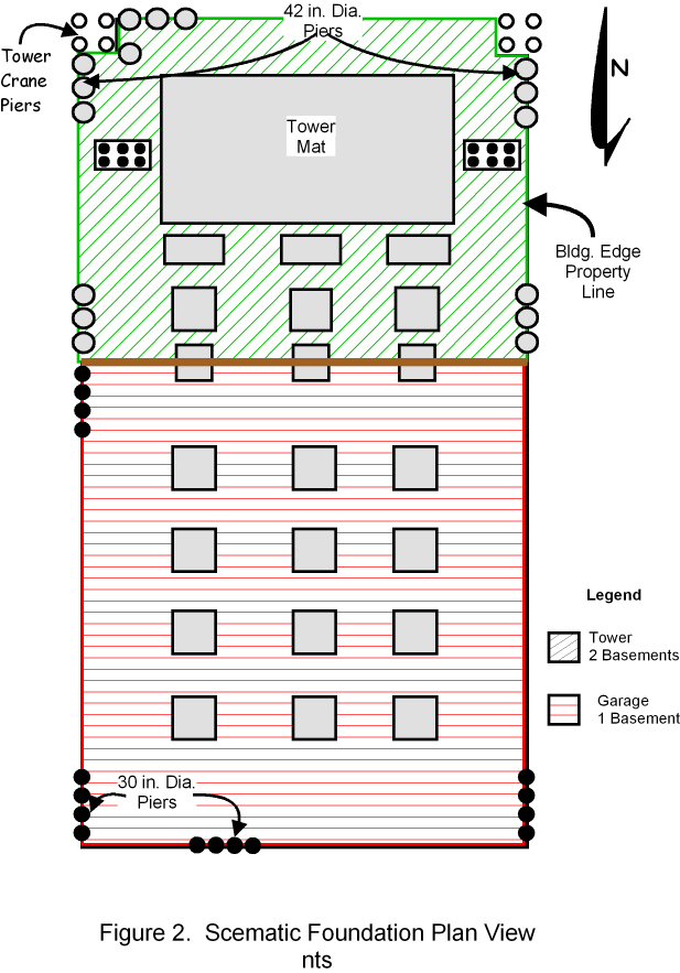
The building has 500,000 gsf (46,500 sq. m.) of medical office space with garage parking for 2,500 vehicles. The entire structure extends over two city business district blocks, covering a total of 1.5 million sq. ft. (140,000 sq. m.). The parking garage is the largest modern garage of its kind built in Houston. The reinforced concrete tower rises 32 floors above a two-level basement, which boasts an excavation depth of 29 ft. (9m) to the base of foundation. Six parking levels and one basement level extend 250 ft. (76 m) south of the tower’s south face. The garage basement extends into the tower so that two basement levels are beneath the tower and part of the garage (Figure 1). Finished floor levels of basement level 2 and Basement Level 1 are 22 ft. (7m) and 12 ft. (4m), respectively.
An excavation retention system was needed because the project extended all the way to the property lines of the Texas Medical Center and the most heavily traveled streets which featured an extensive network of utilities. To minimize the use of property for temporary excavation retention and guarantee a cost-effective plan, we designed the underground structure to function both temporarily and permanently. Drilled piers of 42 in. (110 cm.) in diameter were selected for the temporary basement wall to satisfy both the requirements of the construction cantilever wall design, and the support of the perimeter columns.
Accordingly, the exterior columns for the tower and garage were supported on the basement wall to avoid cantilevering the structure floors, and reducing the interference of perimeter columns on the north, east, and west sided of the tower (Figure 2). The south side perimeter columns at the garage transition are supported by large spread footings. A mat foundation is used to support the Tower core. Intermediate columns along to east-west axis are supported by drilled pier groups.
Foundation Characteristics
The foundation development is divided into five systems:
- Drilled piers, 42 in. diameters, arranged as a cantilever in a single line group along three sides formed the temporary excavation wall, permanent basement wall, and full foundation support for the building and garage exterior columns
- Shallow spread foundations supported the interior garage loads
- Mat foundation supported the interior building core
- Mini mats,30 ft. by 15 ft., supported the exterior building columns bordering the parking garage
- Six pier groups with intermediate columns remained between the mat and basement wall along the east-west building axis
Although the building floor slab in Basement Level 2 is 20 ft. below street level, the building mat foundation base extended 29 ft. below street level, and the garage foundation bases extended from 16 to 18 ft. below street level.
The drilled pier retaining wall along with multiple foundation systems ensured the success of the project because the piers allowed maximum utilization of the property. Although we considered auger casts in place piles, we eventually chose drilled piers installed by the slurry displacement method. We chose this method because it involved fewer variables to control at the construction site and could guarantee steadfast results by allowing us to install reinforcements before concrete instead of after grouting.
The edge of the core mat was limited because the pier cantilever was designed for lateral earth pressure between the street level, the top of the basement level 2 floor slabs, and the axial loads from the structures. Pier sections were 42 in. dia. by 86 ft. bordering basement level 2, and 30 in. dia. by 40 ft. along the parking garage basement level 1.
Drilled Piers
A total of 379 piers were installed by the slurry displacement method consistent with ACI 336.1-89 and 01, the placement of these piers was based on a plan created by the design geotechnical engineer, and aligned with all project specifications. Nearly 180 piers were 42 in. dia., by 70 to 120 ft., to support the exterior columns of the 30-story building, act as the temporary excavation wall, and act as a permanent basement wall. A total of 202 piers at 30 in. dia. were installed to depths ranging from 37 to 92 ft., achieving the same objectives in a one story basement as large diameter piers.
Pier clear spacing was typically 18 in. Reinforcing amounted to 1.2 to 1.3% of the pier cross sectional area using an asymmetrical spacing for efficient use of pier reinforcing steel. Although the reinforcing spacing was initially designed for a minimum clear spacing of 4 in., or 4 times the size of the maximum coarse aggregate, the geotechnical engineer acquiesced to a smaller clear spacing of 3 in. This was consistent with past positive experiences that results in strong on-site construction engineering.
Pier Concrete
The pier concrete mix (Table1) was used successfully on past projects with the supplier. The same mix was again confirmed to be suitable using a trial batch that maintained a 6 in. slump for 4 hours. This test was necessary because cement manufacturers and mid-range retarder product manufacturers changed since the last use of the mix with design properties.

General Subsurface Conditions
The general subsurface conditions are variable soil borings, consistent for Houston Area deep excavations (Table 2). Beyond the surface fill, the underlying soils are medium to strong clay, with sand and silt inclusions at varying thicknesses and positions. From the base of the fill to about 30 ft. below street level, the soil is clay with a distinct, but discontinuous, silt zone from 70 to 80 ft. below street level. The clay grades to dense, silty fine sand below 30 ft. to about 60 ft. Only strong clay lies below the level of sand.
The shear strength of the clay soils below around 10 ft. is more than 0.7 tsf, and becomes more than 1.0 tsf below the upper sand. The sand and silt is medium dense to dense in condition provided the groundwater is controlled properly during site excavation. The sand and deep clay has siltstone inclusions at varying positions, but generally smaller than 2 ft. The depth to ground water on site was measured to be 24 ft. below the ground surface in the upper sand, and slightly deeper in the zone from 70 to 80 ft. depth.


Foundation Features
The shallow foundations in the structure interior consisted of a core mat for the tower, mini mats of 15 by 30 ft., and spread footings of 12 ft. by 12 ft. The tower mat was designed using the DAM procedure initially reported by Ulrich (1995) for the design of mat foundations and adjusted utilizing local experience with tall buildings. The building foundation movement assessment was analyzed by extending the DAM procedure to the perimeter walls considering Busssinesq and Wetergarrd Models. The expected differential movement between the basement wall and tower core of less than 1 in. was achieved by top out in June 2006.
Groundwater Level Control
Proper control of the groundwater is needed for both construction and long term conditions. Inadequate groundwater control would cause the excavation to be unstable and the mat subgrade would quickly result in catastrophic building performance. A system of 8 deep, fully-penetrating wells with submersible pumps was installed outside of the tower to depressurize and dewater the building excavation.
The temporary dewatering was not designed to allow drilled pier installation by the dry methods because local experience has shown that the dewatering system is seldom effective in preventing premature collapse of the shafts below the original groundwater level. Combined flow to the discharge location was 70 to 80 gpm. The temporary system was replaced by an under-slab gravity system using a double stage sand and gravel filter to PVC collector pipes designed and detailed by the geotechnical engineer.
Drilled Pier Construction
Drilled pier construction followed the project specifications prepared by the design geotechnical engineer in general accordance with ACI 336.1- (01). This was first used in Texas to define the pier construction method on major Texas projects (Ulrich, 1990, 1995). Before the emergence of the new ACI pier construction standard, piers installed by the slurry displacement method were popular primarily with the Texas Department of Transportation and in Florida.
The principal parameters measured on this assignment were mud weight, mud viscosity, tremie tip position, and concrete flow characteristics. Concrete delivered to the pumping location not containing at least a 7 in. slump was rejected. Except for six piers wherein the concrete was not expunged beyond the top of concrete, all piers were clean smooth and free of significant defects to the depth exposed in the excavation.


Example of an occasional hole only extending to the rebar.
The drilled pier installation process and results were an awesome improvement over the results which occurred without a responsible pier installation standard and superior construction engineering (Figure 8).
Contact our firm today to learn more about our participation in some of Houston’s most impressive construction projects. You can access our convenient contact form here. Our service area includes the entire South of Texas, as well as the rest of the U.S.